Kimark Smart Flare (KSF)
- Gas Flow Measurement and Accumulation Is Standard
- Interchangeable Flare Stacks
- Modbus Communications
- Control and Logging
About
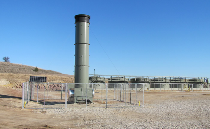
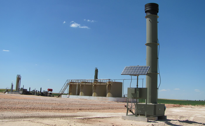
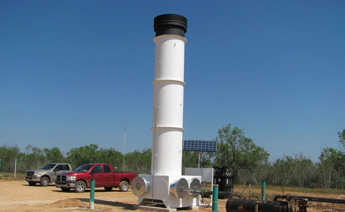
Various Smart Flare Installations
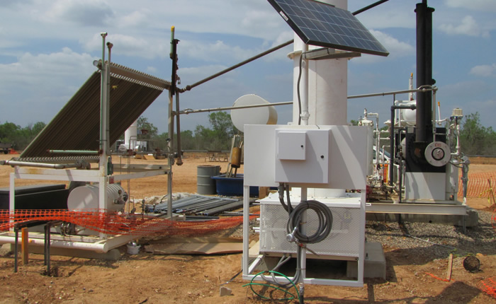
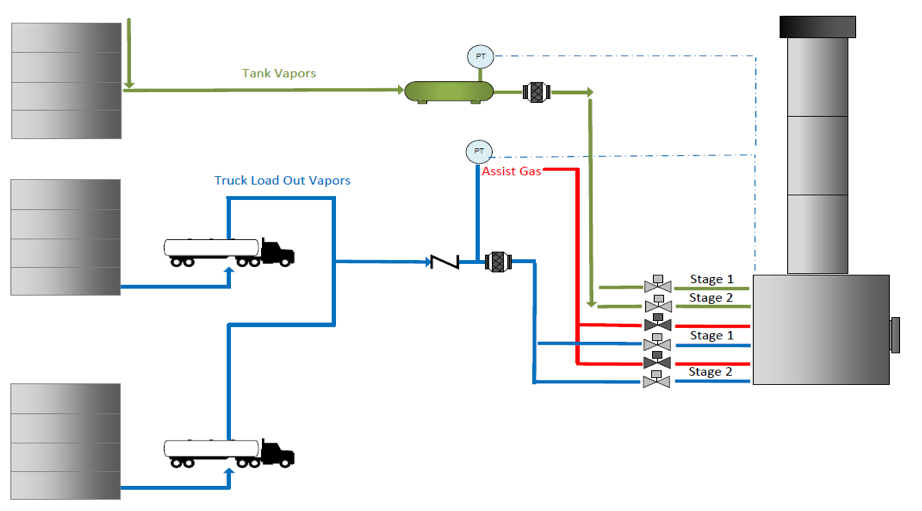
SmartFlare for truck unloading
Sizes
| Size of outer diameter | Flow rate in MCFD |
|---|---|
| 26″ | 30 |
| 33″ | 50 |
| 48″ | 100 |
| 64″ | 280 |
Concept
To burn VOC (Volatile Organic Compound) gases from condensate and water tanks and eliminate venting VOC gasses to the atmosphere, keeping the customer in compliance with the heavy industry regulations.
By installing a low pressure sensor measured in ounces on the common manifold piping of the tank battery, the flare senses a rise in pressure and starts the burn sequence. With adjustable start and stop set points, the amount of PSI on the tanks and temperature of the burn can be controlled. An example would be: “ON” at six ounces and “OFF” at two ounces to keep the burn temperature at nominal.
- The low profile of the enclosed flare and quiet running make it advantageous for use in both rural and populated areas.
- The SmartFlare is designed to operate in multiple conditions. It can be a stand-alone controller for production vessels, responding to the fluctuation of gas vapors. In addition, it is a relief system for tank batteries with vapor recovery units that may not be able to handle unusual surges of gas.
- Solar powered, eliminating the need for purchase power.
- Low power fast-acting electric motor actuator. This allows for opening and closing without the use of venting solenoids.
- High turndown ratio via multiple stages/burners with programmable start/stop points.
- Multi-stage capabilities allow for customization. This includes BTEX combustors for dehy’s/amine plants, higher/split pressure dual stream units for truck loading/unloading stations, as well as extending operability of the unit thru the entire life-cycle of the well or facility.
Features
UV Flame Detector
The Kimark UV Flame Detector senses flame presence and intensity. Upon a failure to see flame, the flare controller goes through a user configurable sequence of timed retries.
Solar Powered
The standard unit is powered by 12 Volts DC, making solar charging an easy option for remote, or non powered applications. Other power combinations are also readily available.
Quiet Operation
The low profile of the enclosed flare and quiet running make it advantageous for use in both rural and populated areas.
No Vent Lines
Low power, fast acting electric motor actuator. This allows for opening and closing without the use of venting solenoids.
Touch Screen Interface
The touch-screen interface is used to configure and monitor all flare functions.
SCADA
Built in Modbus communications for simple access with SCADA systems. The user can enter setup parameters from a simple, intuitive communication menu and be able to retrieve data within minutes.
Gas Flow Management
The ability to measure gas flow built into all of our SmartFlare Panels. Gas accumulation is measured in current rate, previous day, and previous hour increments.
Onboard Logging
The unit continually monitors temperature, pressure, and runtime. This is then logged to a two gigabyte memory chip which can be easily transferred to a computer and viewed as a standard .CSV file (Excel).
Operation
Configuration
Operation of the unit
By installing a low pressure sensor measured in ounces on the common manifold piping of the tank battery, the flare senses a rise in pressure and starts the burn sequence. With adjustable start and stop set points, the amount of PSI on the tanks and temperature of the burn can be controlled. An example would be: “ON” at six ounces and “OFF” at two ounces to keep the burn temperature at nominal.
The Kimark UV Flame Detector senses flame presence and intensity. Upon a failure to see flame, the flare controller goes through a user configurable sequence of timed retries. If for any reason power is disrupted to the flare unit and returns, a purge sequence will be implemented to prevent premature ignition of the flare.
The unit continually monitors temperature, pressure, and runtime. This is then logged to a two gigabyte memory chip which can be easily transferred to a computer and viewed as a standard .CSV file (Excel).